Den's dial up project
I was inspired by one of my usual timewasting rabbit-hole adventures on Wikipedia. I was reading about how dialup works, as I never fully grasped as to what kind of machine my PC was dialing into for me to go on the interwebs.
For those that don’t know the specifics, a quick overview of how dial-up generally worked: your PC used its modem to call a modem at you ISP’s location, it would negotiate a connection (those mystical sounds that we heard) and access the internet using a protocol known as Point-to-Point protocol PPP)
I figured I would give it a shot after reading over a few sites. I TAKE NO CREDIT FOR THEIR WORK!
https://dogemicrosystems.ca/wiki/Dial-up_pool
https://gekk.info/articles/ras.html
First I would use the modem in my laptop as it was the only computer I own that had a modem I know worked.
As for what I was calling into, I was following the guide at gekk and researched these Integrated Access Devices (IAD) that could not only call other extensions (8-24 analog/FXS ports), but could also do VoIP and PRI T1 and route calls to/from any. Doge made a write up using an Asterisk server, but I was intrigued by these IADs.
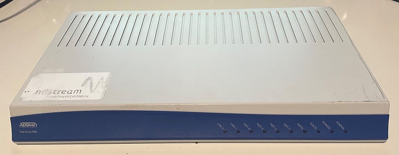
I picked up this Adtran TA908e for about $15 on eBay


PBX in a box!
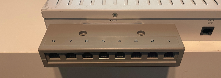
Having 8 FXS ports are more than enough. I have attached a “telco harmonica” to the Amphenol voice connection as opposed to using a breakout cable to keep things cleaner.

After factory resetting the 908e, setup was normal. DHCP, DNS, etc. I used the internal connection test to verify I had internet.
Next thing I worked on was getting the FXS ports working. I set them up so one of them is 101, and the other is 102. They are just extensions, but this way, I can simulate a true POTS phone network without using a phone line simulator. It is a switch/central office. Pure analog, no VoIP.
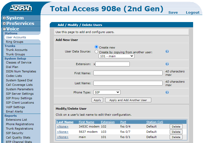
Extension 101 is where I am calling from. Ex 102 and 103 are answering modems.
So I have a way to call a device. For the answering modem, I got a US Robotics 3453 from ebay. It is not a “softmodem” so there is maximum compatibility, as I planned to use on an Linux server. Guides everywhere on doing it with Windows, but doges is thorough for Linux.
I first connected the modem to an open USB port on the server with a DB255 to DB9 adapter then that to a USB adapter. The phone port was connected with RJ11 terminated phone line. Ext 102 to the 3453. I did add 103 for a USB modem (USR 5637)
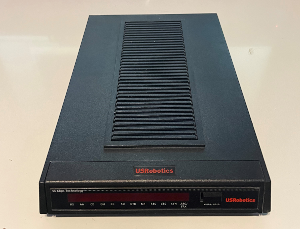
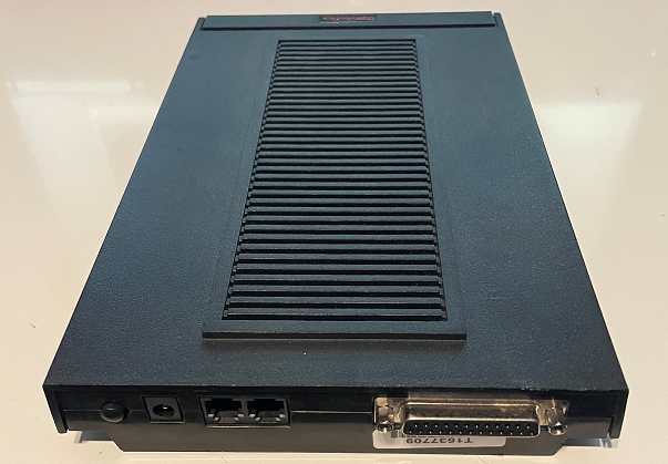
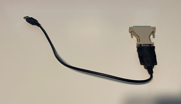
Now we have the connections made, we have to finish setting up the ISP side.
Server
For this I’m using Ubuntu and went along with Doge's guide.
With this setup, your connection will not exceed 33.6k. This because of the analog/digital conversion happening at both ends. More on this below.
Now say you wanted to have more than one modem. For this setup, you can do this with as many modems as you have ports/adapters. You would add additional ports in the mgetty config, but extend the ring time incrementally to how many modems you have. You would also need to create additional devices in ppp with a different IP range. You may also need additional users, as my modems wouldn't answer if the user was still connected.
So how would ISPs do this? Well, I have read various postings about folks with access to a T1 line doing just that, having a closet with a bunch of modems. From reading gekk's site and additional research, there was seemingly simple but specialized equipment to do this.
Having a modem bank that can be racked and house a number of modems.


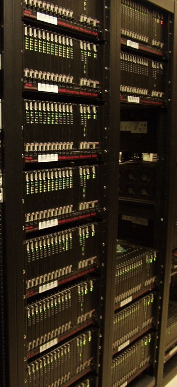
I assume they had a T1 line broken out to phone lines and the modems would answer in order.
Still there would be a bit of cabling required. Each of those serial ports would need to connect to some sort of computer/routing device. This is where a company known as Livingston (Lucent) made a device called a Portmaster. There were 4 models. I could not find anything clear about using the first one for a setup such as this, but the second and third seem common. The fourth was a carrier class/high density device that is beyond what I wanted to venture into.
Configuration was done command line or a basic GUI.
First the Portmaster 2 (specifically the PM-2E)
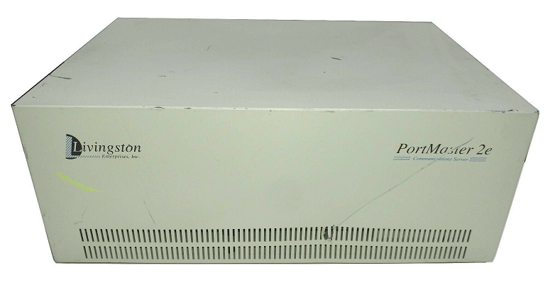
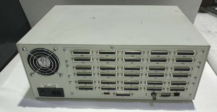
All those serial ports is where you would connect the modems to, whether from a modem bank or individually. The internet connection was fed into one of the Ethernet ports (10BASE2, 10BASE5, or 10BASET, to fit various installations.) Note that it is modular and you can swap out one of the cards (10 serial ports) in exchange for a card that has BRI ports.
This is still analog. How about digital modems? This is where V.90/K56flex were used.
Portmaster 3
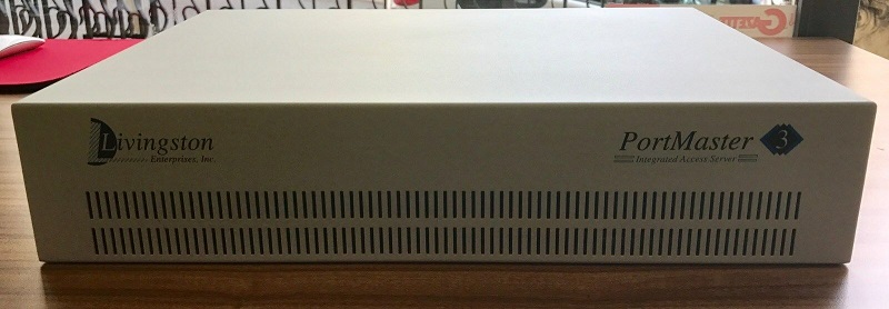

Six slots, standard was the MDM-56K-8 cards that contained 8 modems - so this box could handle 48 calls.
Before explaining how the calls came into the box, a quick explanation how V.90/K56flex got those speeds above 33.6. An ISP could have a digital connection via T1, which was much more efficient. A T1 can carry 24 calls digitally over two twisted pairs. This means there was no additional conversion and a full T1 channel could be used (1 channel = 64kbits - 8kbits signaling = 56kbits for use) and converting from digital to analog caused no loss serious enough to affect the speed, but the same could not be said for analog to digital. Since there was never a feasible method found by the time dial-up was on its way out, upstream using typical consumer modems never went above 33.6kbps. The V.92 standard allowed for up to 48kbps, but was not seen until closer to the end of dial-up popularity.
So the Portmaster 3 would be connected via a T1 line (or two) from the telco for calls. A 2U size device that could handle 48 subscribers.
Manufacturers found ways to increase density further. Gekk mentioned Cisco and Patton.
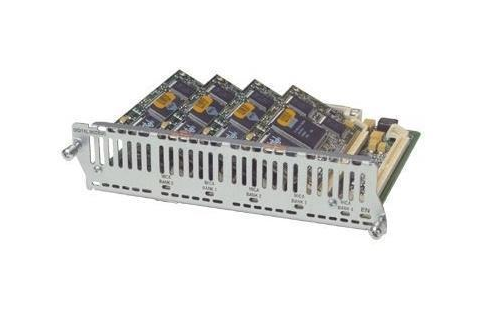
Cisco did this with analog (NM-16AM) and digital (NM-24DM) expansion cards for their routers.
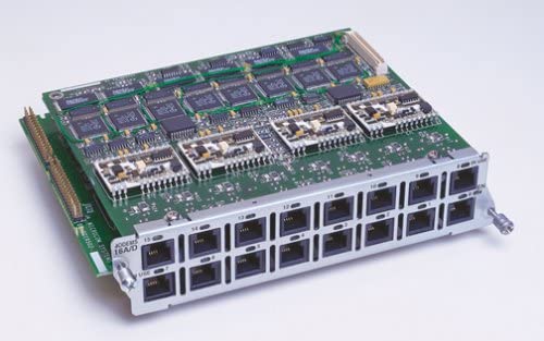
Patton electronics is a company I had not heard of until getting into this project. They specialize in connecting anything to just about anything. Focusing on their dial-up access devices they named "dialfire"
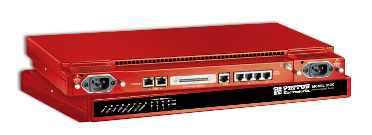
These things can take up to 96 subscribers in a 1U case with their 4 T1 connections. They also make server expansion cards that can be installed in any server.
I figured it would be a cool project to expand upon with these various devices. The Patton really intrigued me, as this was an ISP grade access server and I was sure I could find one. Endless searching turned up nothing.
I then decided to focus on Cisco. I snagged a 3945 ISR for less than $50 that was already loaded with voice DSPs. Since it came with no other expansion cards, I got two T1 cards and one of the analog NM-16AM modules, with plans to get a digital one later.


Modules installed in the 3945.
I could send calls to it from the Adtran.
Little did I know what a pain it would be. Knowing nothing about Cisco's IOS, I tried to learn it. This is also where I learned that you're on your own for software/upgrades due to their licensing model. I just couldn't find the time to get into it.
I finally lucked out with finding a Patton 2960 RAS
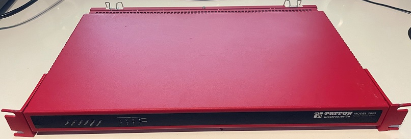
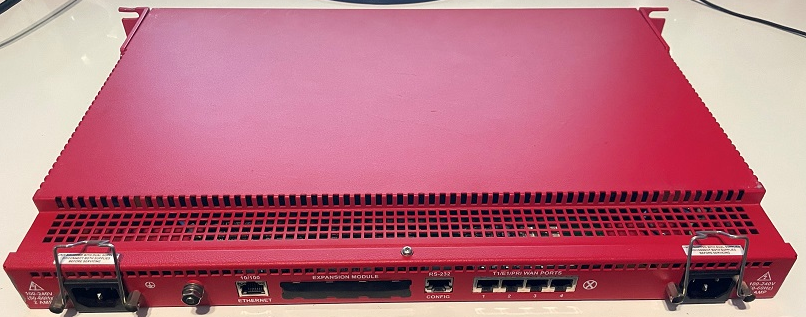
This has the digital modems and only accepts a T1 connection. I will use the Adtran to send calls over T1 to it. Since a T1 line is just two twisted pairs, I made my own link.
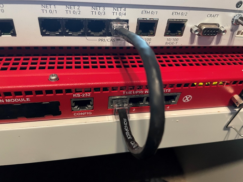
I am going directly from one device to another, so this had to be crossover wired. The Adtran will be configured to send calls to ext 111 over PRI
Now to configure the Patton after a factory reset.
Not a fancy web interface, but it works. It can also call out for connecting to BBSs

Following Patton's guide, I set up users under authentication and the T1 link, as well as the dial in settings which were mostly left untouched.
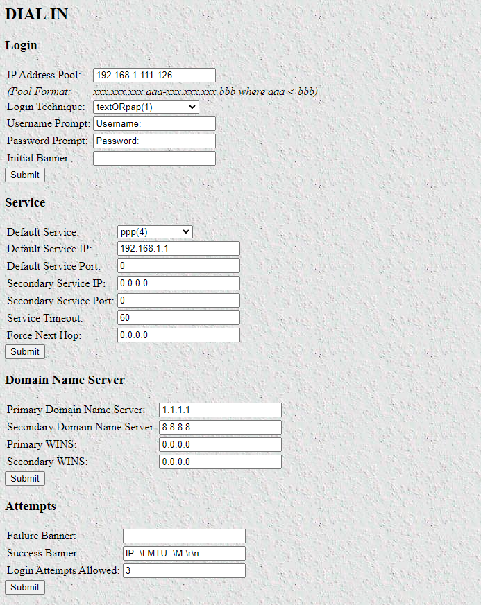
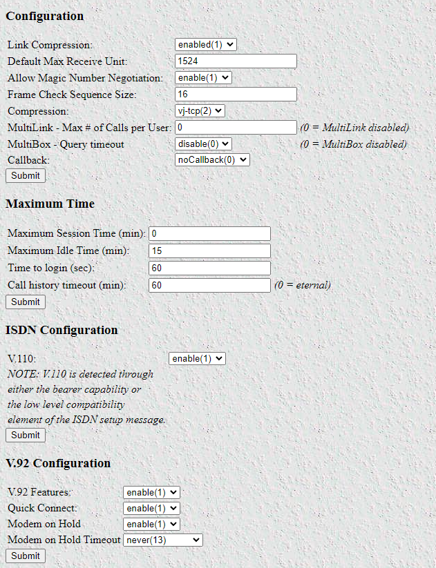
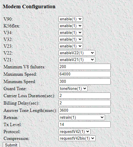
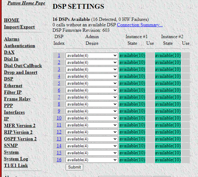
The digital modems are actually DSPs as they aren't converting the signals from digital to analog and vice versa. This 2960 has 16 installed.
To get the full experience I never had, I got a couple external modems - another 3453 as well as its successor (per USR's site) the 5686G
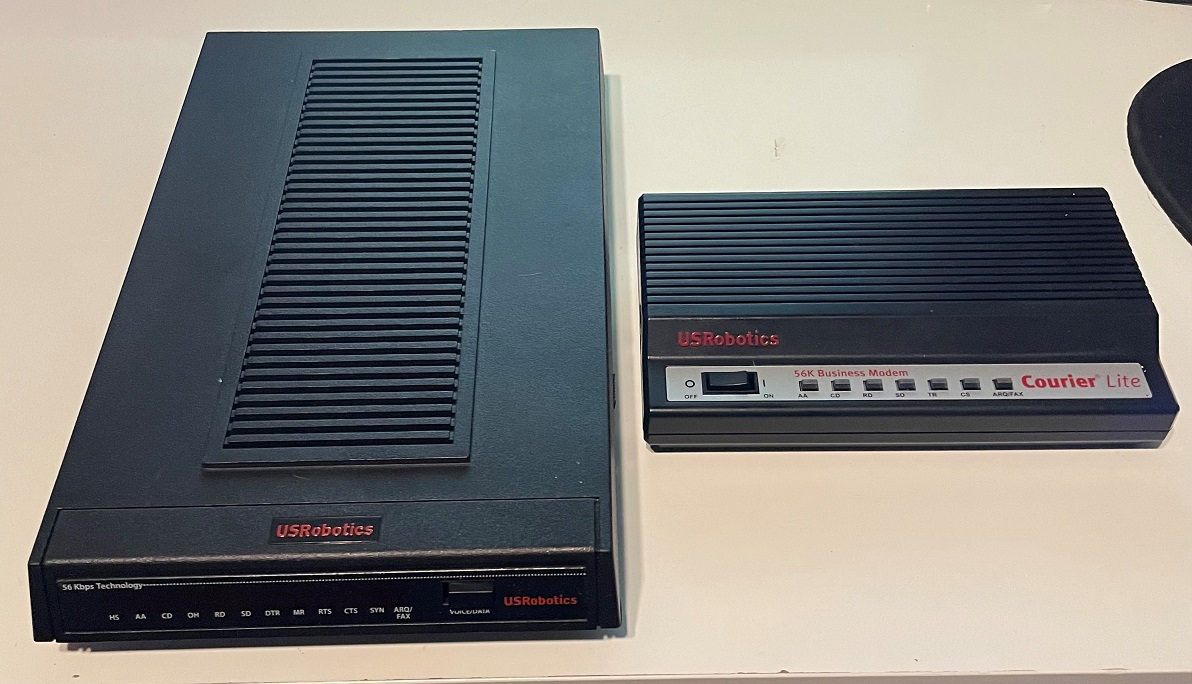
I tried each with another set of adapters connected to my laptop and see how the connections would go. As expected, each modem would consistently get 33.6 when calling the receiving 3453. The (slight) difference was when calling the Patton with the digital connection.
The internal and the 5686G would get 52.0, while the 3453 would get the full theoretical maximum of 53.3Kbps. Woo!
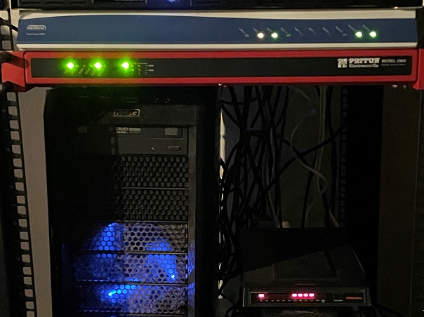
Here is the equipment installed. Please excuse the dust and wiring!
